
Introduction
State the function of motor in circuit breaker drive and the answer becomes much easier once you separate the motor operator mechanism from a motor protection circuit breaker (MPCB). In a circuit breaker drive, the motor’s main function is to store or restore mechanical energy inside the breaker operating mechanism so the breaker can be closed reliably, operated remotely, and made ready for the next switching cycle. In many designs, the motor does this by charging the closing spring or by supporting an automatic accumulation of energy arrangement in the breaker drive.
This is where many readers get confused. A motor protection circuit breaker is designed to protect an electric motor load from overload, short circuit, and phase failure. A motor in a circuit breaker drive, by contrast, is part of the breaker operating mechanism itself. It helps the breaker switch on, switch off, and remain mechanically ready for operation through a stored energy mechanism, often alongside accessories such as shunt trip, undervoltage release, and auxiliary control elements.
That distinction matters for SEO, for technical clarity, and for anyone trying to understand what happens inside real breaker assemblies such as motor drive control for circuit breakers, including families and document references like MP-BH-X230, BH630N, and BH630S.
What Is the Function of the Motor in a Circuit Breaker Drive?
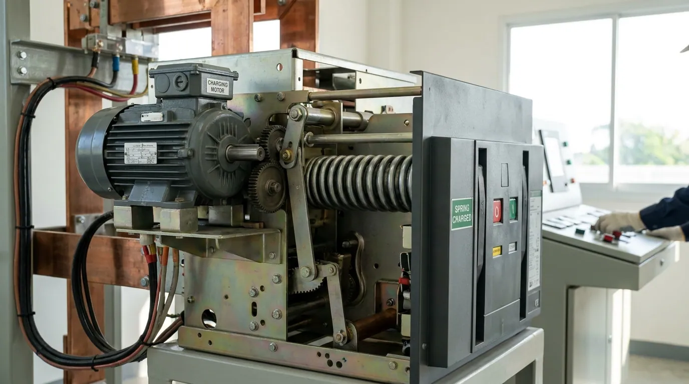
The function of motor in circuit breaker drive is to provide the mechanical preparation needed for fast and reliable operation. In plain terms, the motor usually charges the spring or builds up stored mechanical energy inside the breaker. When a closing command arrives, that stored energy is released so the breaker can close with the speed and force required by its design. After the breaker operates, the motor often runs again to recharge the mechanism and return the breaker to a ready-to-close condition.
This is why the breaker motor is often linked with terms like stored energy, breaker loading, automatic accumulation of energy, and remote control of circuit breaker. The motor is not normally the component that directly performs fault sensing. It is the mechanism that ensures the breaker has the operating energy needed to act when commanded. That is a major difference from protection-focused devices like MPCB units, which are designed around overload protection, short-circuit protection, and phase failure protection.
Think of the motor as the system’s energy preparer. Without it, the breaker may still work manually in some designs, but it loses much of the convenience and reliability tied to remote electrical operation, repeat switching, and automatic readiness. In larger installations, that can affect operational continuity, system reliability, and even the layout of the overall panel design.
How the Stored Energy Mechanism Works
To understand how does a motor drive operate a circuit breaker, it helps to follow the sequence step by step.
First, a suitable control voltage is applied to the motor drive. Depending on the breaker design, this might be 24 V, 48 V, 110 V, 230 V AC, or 220 V DC. The motor then runs and drives the mechanism that builds up stored energy in the breaker. In many practical arrangements, this means the motor charges a closing spring until the breaker reaches a loaded state.
Second, once the mechanism is fully charged, the breaker enters a ready-to-close condition. A control command can then trigger the closing sequence. At this point, the energy that was accumulated by the motor is released through the operating mechanism, which closes the breaker quickly and consistently. This is why people often describe the motor as the part that charges the closing spring rather than the part that performs the actual closing stroke by itself.
Third, after a switching action or trip event, the motor may start again and re-accumulate stored energy so the breaker can be used for the next operation. That is one reason phrases like circuit breaker loading, breaker closing spring recharge, and motor operator reset function matter so much in this topic. The goal is not just one successful close. The goal is to keep the breaker ready for the next cycle with minimal delay. Some documentation also references recommended control impulses greater than 100 ms, and breaker families may be offered in 3P and 4P configurations depending on the application.
A simple way to summarize it is this:
| Step | What the motor does | Why it matters |
|---|---|---|
| 1 | Receives control voltage | Starts the drive sequence |
| 2 | Builds stored mechanical energy | Prepares the breaker for operation |
| 3 | Charges the closing spring or equivalent mechanism | Creates fast, reliable closing force |
| 4 | Restores readiness after operation | Supports repeated and remote use |
That is the heart of the answer to what is the purpose of motor control in a breaker drive assembly.
Motor vs. Trip Coil vs. Closing Coil
One of the biggest gaps in competitor content is the lack of a clean explanation of trip coil vs motor and closing coil vs motor.
The motor is mainly there to build up stored energy. It is associated with loading, charging, and restoring the breaker to a ready condition. The trip coil or shunt trip is different. It is used to release the tripping mechanism so the breaker opens when commanded. The closing coil is different again. It helps trigger the closing action by releasing the already stored energy in the correct way. Meanwhile, an undervoltage release is used to make sure the breaker behaves safely when supply voltage drops below the allowed level.
So if someone asks, why is a motor used in a circuit breaker drive, the answer is not “to detect a fault.” The answer is that the motor helps prepare the operating mechanism. If someone asks, what directly trips or closes the breaker, that answer normally points to the trip/close release devices, not the charging motor itself.
This distinction is useful in troubleshooting too. If the motor runs but the breaker does not close, the fault may be in the closing release, an interlock, a control circuit, or an accessory state. If the breaker will not trip electrically, the issue may lie in the shunt trip, undervoltage release, or related control wiring rather than the motor.
Why a Motorized Breaker Drive Matters in Real Systems
In real installations, the value of a motorized breaker operation system goes beyond convenience. It enables remote switch on / switch off control, reduces dependence on manual operation, and supports safer switching where direct access to the breaker is limited. In some product documents, this appears as AUTO/MANUAL mode, remote switch off/on, or similar operating language.
This matters in industrial automation, switchgear, standby units, and larger control panels. In these environments, operators may need the breaker to close from a control room, respond to supervisory control logic, or restore readiness after a prior trip without hands-on intervention. A motorized drive improves maintenance efficiency and system reliability because it reduces the number of purely manual steps required for normal service.
Here is a useful working quote for the article:
The motor does not replace breaker protection; it prepares the breaker mechanism so switching can occur quickly, remotely, and repeatedly.
That single idea captures why the motor is central to the breaker operator assembly but not the same thing as a protective release.
When the Motor Runs but the Breaker Is Not Ready to Close
A very practical question is: what happens when the motor drive is not loaded in a circuit breaker?
If the motor runs but the breaker remains unavailable, the problem is often related to incomplete loading, a failed ready-to-close contact, an interlock issue, or a problem in the control accessories. Some motor drive references explicitly note that it is not possible to switch on the circuit breaker when the motor drive is not loaded. That gives you a direct clue: motor movement alone is not enough. The mechanism must reach the correct charged state.
A few common causes include missing or incorrect control voltage, worn linkage parts, defective auxiliary switches, release accessories holding the breaker in a blocked condition, or failed limit switch behavior. In practical terms, a technician may also inspect whether the breaker can be moved through manual spring charging or manual operation to separate a power problem from a mechanical one.
This is where terms like trip indication, breaker loading, manual backup operation, and motor mechanism interlocks become useful. They are not just SEO phrases. They reflect the real questions maintenance staff ask when the breaker is not behaving as expected.
How This Differs from a Motor Protection Circuit Breaker
Because several topically related competitor pages focus on motor circuit breaker or motor protection circuit breaker topics, your article needs a clear comparison section. This is likely one of the strongest content-gap opportunities.
A motor protection circuit breaker or MPCB is installed to protect an electric motor from conditions such as overload, short circuit, and phase loss. These devices are associated with ratings and standards, such as 32A, 50kA @ 480V, or UL 60947-4-1A Type E, depending on the product line. They are about protecting the load.
A breaker drive motor, on the other hand, is part of the breaker’s operating mechanism. Its job is not to protect a motor load. Its job is to prepare the breaker to operate by storing energy, enabling remote control, and helping the breaker recover readiness after a prior operation.
| Feature | Motor Protection Circuit Breaker (MPCB) | Motor in Circuit Breaker Drive |
|---|---|---|
| Main job | Protects the motor load | Prepares/charges the breaker mechanism |
| Typical concerns | Overload, short circuit, phase failure | Stored energy, closing spring, remote operation |
| User intent | Protection and sizing | Mechanism function and switching readiness |
| Common keywords | MPCB, motor protection, phase loss | motor operator, stored energy mechanism, breaker loading |
This table helps searchers who land on mixed SERPs and are not sure which device the page is talking about.
Applications of Breaker Drive Motors
The function of motor in circuit breaker drive becomes especially important in systems where frequent or remote operation is needed. Examples include switchgear lineups, automation panels, standby power arrangements, and larger facilities where the breaker is part of a wider control scheme. Product and guide pages across the competitor set repeatedly mention contexts like industrial automation, HVAC, pumps, compressors, conveyors, and broader industrial control setups. Even though those pages often discuss protection rather than drive motors, they confirm the kinds of environments where electrically operated breaker mechanisms matter.
In a plant with complex distribution, a breaker might need to close on command from a remote station. In a standby arrangement, it may need to transition as part of a larger control sequence. In such cases, the motor operator accessory supports operational continuity, reduces manual intervention, and helps the breaker remain ready for service.
Some assemblies may also be specified by pole arrangement such as 3P or 4P, and in building-scale systems you may hear about 200-amp panel or 400-amp panel contexts when discussing breaker installation environments more generally. Those phrases are not the definition of the motor drive, but they widen the semantic footprint of the article in a natural way.
Selection Factors: What to Check Before Choosing a Breaker Motor Drive
Even an informational article benefits from a light commercial section, because readers often want to know what matters when selecting a motorized operating mechanism.
The first factor is control voltage compatibility. The motor drive must match the available supply, whether that is 24 V, 48 V, 110 V, 230 V AC, or 220 V DC. The wrong supply can prevent correct operation or cause unreliable behavior.
The second factor is mechanical compatibility. The motor operator must match the breaker family, frame, and accessory scheme. That is where model references like MP-BH-X230, BH630N, and BH630S become relevant. A drive designed for one breaker family is not automatically suitable for another.
The third factor is the accessory ecosystem. You may need compatibility with shunt trip, undervoltage release, auxiliary contacts, signaling functions, and cycle-counting or status features. In some technical references, connectors and terminals are identified with designations such as X3, X4, A1, A2, B1, B2, S5, S6, F67, and F68. Those details are more product-specific than general, but they show how deeply the motor drive can be integrated into the control circuit.
Quick Troubleshooting Checklist
When a circuit breaker motor mechanism is not working as expected, a short checklist can save time.
First, verify the control voltage and make sure it matches the required rating. Second, confirm the breaker has actually reached a loaded or ready-to-close condition. Third, inspect any shunt trip, undervoltage release, or other interlocks that may be preventing operation. Fourth, test whether manual spring charging or manual operation is possible. Fifth, check whether the cycle or status indicators show abnormal behavior. Some systems include a counter of cycles or status signals that can help identify repeated or incomplete operation.
A practical checklist like this gives the article more real-world value than a definition-only piece, and that is exactly the kind of utility missing from many of the existing competitor pages.
Mini Case Example
Imagine a facility breaker that uses a motor operator with 230 V AC control power. The motor runs after a trip, but the breaker still cannot close remotely. A quick review shows the mechanism never reaches the fully loaded state, so the ready-to-close condition is never achieved. In that case, the motor is doing part of its job, but the operating sequence is incomplete. The root cause might be a mechanical obstruction, an interlock, or a failure in the charging indication path. This example highlights a key point: the motor’s function is not just to turn. Its function is to prepare the breaker mechanism correctly and completely.
Frequently Asked Questions
What is the main function of the motor in a circuit breaker drive?
Its main function is to store or restore operating energy in the breaker mechanism, often by charging a spring, so the breaker can close reliably and remain ready for remote or repeated operation.
Does the motor trip the breaker directly?
Usually, no. The motor mainly charges the mechanism. Tripping is typically handled by components such as shunt trip or other release devices.
What is the difference between a motor operator and an MPCB?
A motor operator helps operate the breaker mechanism. An MPCB protects a motor load from faults like overload and short circuit.
Can a breaker still be operated manually if the motor fails?
In many designs, yes, at least to some extent, through manual control or manual spring charging, but that depends on the breaker design and accessory arrangement.
Why is the breaker not ready to close after tripping?
Possible reasons include incomplete charging, missing control power, an interlock state, or a fault in the release or signaling accessories.
Conclusion
The best answer to state the function of motor in circuit breaker drive is this: the motor is there to prepare the breaker for operation by building stored mechanical energy, supporting remote control, and restoring the breaker to a ready-to-close state after use. It is a key part of the breaker operating mechanism, not the same thing as a motor protection circuit breaker that protects an electric motor load.
When you explain that clearly—and back it up with practical sections on stored energy, closing spring recharge, trip coil vs motor, control voltage, and troubleshooting—you create a far stronger article than the broader MPCB pages currently dominating related SERPs.
Disclaimer: This article is for general technical and educational purposes only. Circuit breaker mechanisms involve high voltage systems, stored energy components, and safety-critical equipment. Any installation, troubleshooting, or modification should be carried out by qualified electrical engineers or licensed professionals following manufacturer guidelines and applicable electrical standards.